The T1 Groomer (T1 Monitoring DACS) is capable
of monitoring a -20dBdsx (0.3Volt Pulse) T1 signal through a Hi-Z path, without in any way
disturbing the live T1 traffic that is required to be monitored. The T1 connector(s) shall
be RJ45 100 Ohms for T1 (and 120 Ohms for E1) and a "Y" cable is provided
(included) to connect T1 Groomer equipment to the T1 ports that are required to be
monitored.
The equipment offers the user
with complete flexibility to choose and select time-slots from each
of the 16 T1 links that are being monitored, without limitation or
restrictions, through the internal TSI non-blocking switch (data
received by the equipment's 32 T1 receivers) and then aggregate the
selected time-slots to the 4 output T1 ports that shall connect to
the test probes etc.
Additional solutions offered and available for Hi-z
Non-Intrusive Monitoring applications are:
The VCL-MegaConnect, 32 Port T1 monitoring
groomer, occupies only a 2U high rack-space, and is a complete 19-inch standalone unit.
The unit operates on a -48VDC input power-supply (AC input adapter is optional for AC
mains operation).
The system is supplied with an easy to use
Windows (95, 98, Me, XP) Graphical User Interface that provides the USER a complete
control to prepare multiple configuration "maps" and store them as easy
to read data files. It may also accessed using CLI (Command Line Interface) through a
Serial (COM) Port of a PC using HyperTerminal text commands. Dry contact relay alarms are
also available at rear of the system to connect the system to external audio and visual
alarms outputs.
The VCL-MegaConnect, 32 Port T1 monitoring
groomer also has a TCP-IP Access feature which allows the DACS to be connected on a TCP-IP
network (10/100 Base Interface) for remote access for configuration and monitoring using
Telnet.
Applications
- 32 Port (plus 4 ports for connecting to monitoring
equipment) T1 monitoring groomer
- Monitoring of Live Traffic on T1 links which are
to be monitored, non-intrusively (Hi-Z) in both transmit and receive directions.
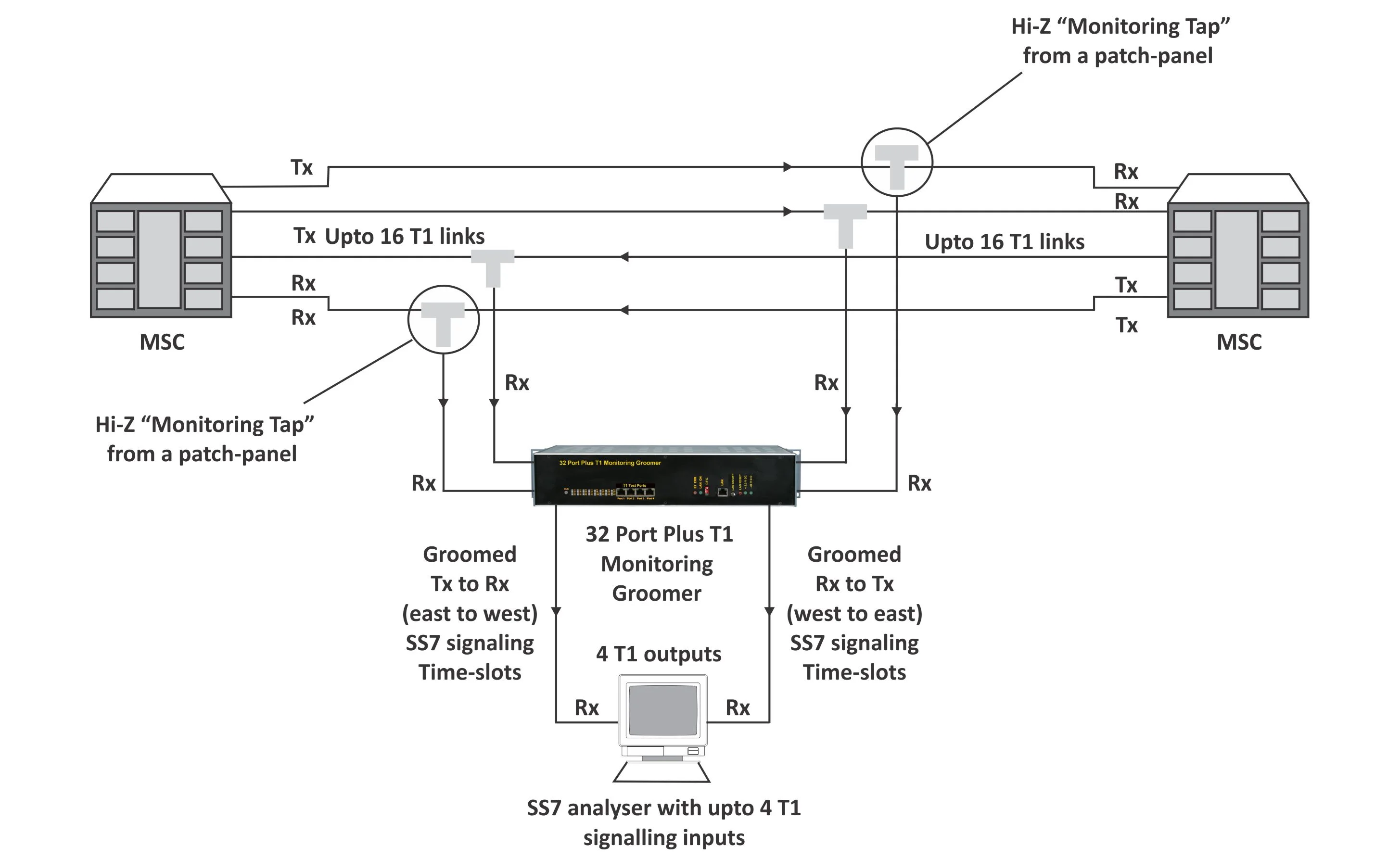
Indications and Alarm Monitoring
- Loss of incoming signal at any T1 Port
- Configuration Error Alarm
- Clock Status
- 1 to 8 channel LED indicators to indicate the status of each
T1 channel
- +3 Volts Power Supply
- -48VDC present
Configuration Error
Programmable Features
- Specifying the priority sequence for clock selection.
- Enabling or disabling T1 channels (masking) of the T1
channels that are not is use.
- Creating a cross - connect between T1s (and E1) at DS-O
level (single time-slot level) using the Windows based, easy to use GUI.
- Telnet interface for remote programming.
Status Monitoring
Related Links
|